
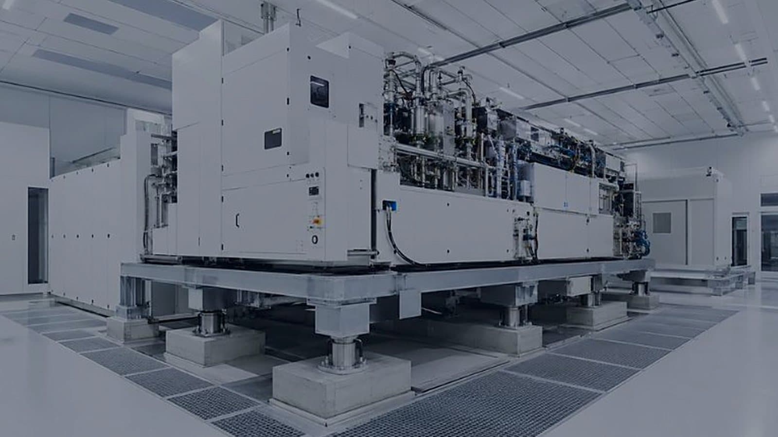
The vibration that upsets a lithography tool often comes from a pump two bays away, through the slab.
Tool vendors give a floor vibration limit, often on the generic VC curves. VC-C is 12.5 µm/s and VC-D is 6.25 µm/s, measured as RMS velocity in one-third octave bands. Those are small numbers. Fans, pumps and compressors run around the clock, and their energy travels through the structure to the floor the tool stands on.
Most of the margin against that limit is won or lost in the layout, so the structural engineer needs to be in the room while the column grid is drawn. In practice heavy rotating plant stays off the slab that carries the litho bay, usually on grade or in a separate plant building. The tool floor itself is often a stiff waffle slab, sometimes with pedestals isolated from the building frame. And a pipe or duct that crosses from a vibrating support to a quiet one needs a flexible connection at the crossing.
Springs and inertia bases added after the slab is poured do help. They are also fixing a layout nobody checked. The trade-off is plant space and structural cost early, against a vibration survey and a retrofit before the tool qualifies.
Our semiconductor scope covers ISO Class 1–3 cleanrooms with vibration isolation, UHP utilities and power distribution up to 22 kV.
Industries