Skip to content

Industries

Semiconductor Industry

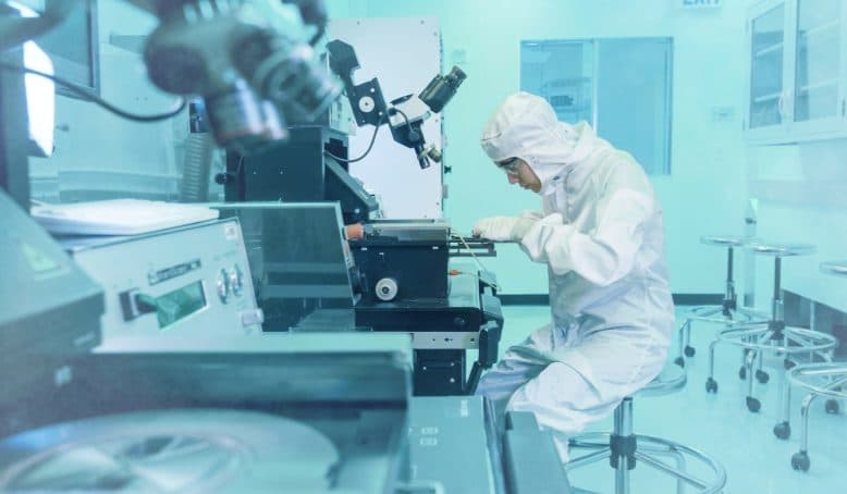
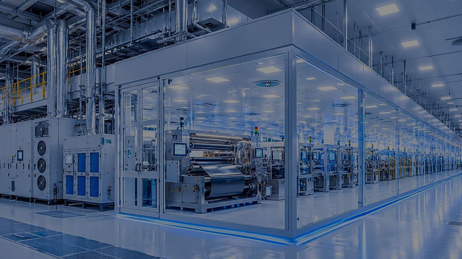
In a fab the facility is not a container for the process — it is part of it, and stability at the tool is what yield is made of. We engineer ultra-clean fabrication environments down to Sub-Class 1 and ISO Class 1–3, with multi-stage HEPA and ULPA filtration and control of airborne molecular contamination.

Industries

Introduction

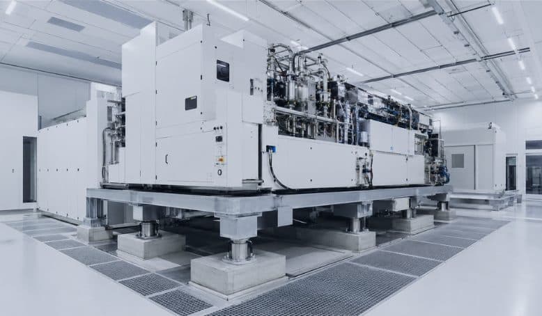
Photolithography and metrology tolerate almost no drift, so temperature and humidity are controlled within micro-environments rather than as a room average, and vibration isolation and equipment foundations are coordinated with the structure rather than added to it. SCADA and facility monitoring keep the whole envelope visible while production runs.

Overview

Environments where the tolerance is the product

In a fab, the facility is not a container for the process — it is part of it. Stability at the tool is what yield is made of.

Semiconductor and advanced electronics manufacturing punishes variation that no other sector would notice. A particle measured in tens of nanometers lands on a wafer and becomes a killer defect. A tenth of a degree of drift across a lithography bay shifts overlay. Airborne molecular contamination at parts-per-billion levels attacks photoresist and copper long before any particle counter reacts. Vibration from a fan two floors away moves a metrology stage past its tolerance.

This changes what the engineering has to deliver. Classification alone is not the specification — the requirement is stability held continuously at the tool, in an environment where equipment is being installed, moved and re-hooked while production continues. Design has to account for the fab's whole operating life, not just its commissioning condition.

We engineer the facility systems that carry that load: ultra-clean air architecture with unidirectional coverage where the process needs it, segmented air handling that isolates bays so work in one does not disturb another, precision temperature and humidity control at the micro-environment level, ultra-high-purity utility distribution, and stable medium-voltage power up to 22 kV with the standby power and power conditioning that protect a tool set from a momentary dip from a momentary dip.

Continuity matters as much as performance. An unplanned excursion in a fab is measured in wafers, and the systems we design are specified for redundancy, for maintainability without a shutdown, and for continuous monitoring that shows a parameter drifting before it crosses a limit.


Capabilities

Scope of work

Precision engineering for semiconductor and high-tech fabrication — ultra-clean environments with tight temperature, humidity, and particulate control for high yield and reliable, uninterrupted operation.

Advanced Nanotechnology Cleanrooms

We design and support ultra-clean fabrication environments down to Sub-Class 1 and ISO Class 1–3. Our engineers manage precise laminar airflow velocities, ultra-low penetration air (ULPA) filtration, and strict electrostatic discharge (ESD) mitigation protocols to protect sensitive electronic assembly.

Ultra-High Purity (UHP) Utilities

Microchip production relies on flawless utility delivery. We design and install high-purity mechanical and electrical systems, ensuring clean utility distribution and highly stable LV to MV power distribution (up to 22 kV) to prevent costly operational interruptions.

Environmental Control & Airborne Contamination Abatement

To prevent microscopic defects on wafers, we integrate advanced HVAC architecture designed to tightly control temperature and humidity while aggressively filtering out particulate and airborne molecular contamination (AMC).

Micro-Environment Temperature & Humidity Control

Photolithography and metrology tolerate almost no drift. We engineer micro-environments and high-precision dehumidification (±2% RH) with tightly controlled temperature stability at the tool and bay level — protecting yield where ambient cleanroom control alone is not enough.

Vibration Isolation & Structural Integration

Nanometer-scale processes are sensitive to the smallest motion. We coordinate vibration isolation, equipment foundations, and structural integration with the mechanical and electrical design — keeping critical tools within tolerance and minimizing transmitted vibration from facility systems.

Facility Monitoring & Automation Systems

Continuous visibility protects continuous production. We deploy SCADA, Facility Monitoring Systems (FMS), and IIoT-enabled controls that track particulate, temperature, humidity, and pressure in real time — with alarming, trending, and audit-ready records to keep sensitive processes stable around the clock.

Our approach

How a fab environment is engineered

The route from tool set and process requirement to a stable, monitored production environment.

  1. Tool set and environmental requirement capture

    Facility requirements are taken from the tool installation manuals and the process itself — cleanliness class by bay, temperature and humidity tolerance, vibration criteria, utility demand, exhaust and abatement duty, and the tolerance for interruption. These become the environmental specification the rest of the design answers to.

    Output

    • Tool facility requirement matrix
    • Environmental specification by zone
    • Utility and exhaust load schedule
  2. Cleanliness architecture and airflow strategy

    Cleanliness is zoned so that the highest classification covers only what needs it. Unidirectional coverage, ceiling filter density, return air path, plenum design and bay-and-chase segregation are set together, along with the strategy for AMC filtration where the process is sensitive to it.

    Output

    • Cleanliness zoning plan
    • Airflow and filter coverage schedule
    • AMC filtration strategy
  3. Thermal, humidity and vibration design

    Temperature and humidity are controlled where the tolerance actually applies — at the tool and in the bay — rather than at a single return sensor. Micro-environment conditioning is designed for the tightest zones, and vibration criteria are addressed through equipment selection, isolation, structural coordination and the routing of rotating plant and services.

    Output

    • Thermal and humidity control strategy
    • Micro-environment design
    • Vibration criteria and isolation coordination
  4. UHP utilities and power distribution

    High-purity utility distribution is designed for the purity that has to survive to the point of use, with material selection, jointing method, dead-leg control and point-of-use filtration specified accordingly. Electrical distribution up to 22 kV is designed with standby, UPS and power quality provision sized to protect the tool set from disturbance.

    Output

    • UHP distribution P&IDs and material specification
    • Exhaust and abatement scheme
    • Single-line diagrams and power quality strategy
  5. Monitoring, automation and continuity

    A facility monitoring system is specified to track particulate, temperature, humidity, differential pressure and utility parameters continuously, with alarm, trending and a record that supports investigation. Redundancy, maintainability under production and controlled failure behavior are designed in rather than assumed.

    Output

    • FMS and SCADA specification
    • Alarm and trending schedule
    • Redundancy and continuity strategy
  6. Commissioning, verification and hook-up support

    Systems are commissioned, balanced and verified against the environmental specification — classification, airflow, recovery, temperature and humidity stability over time, and utility quality at the point of use. Tool hook-up is supported and the environment is re-verified after installation activity.

    Output

    • Commissioning and balancing records
    • Environmental verification report
    • Tool hook-up support and re-verification

Technical parameters

Environmental and utility criteria

Classification limits are from ISO 14644-1. Stability bands are typical fab requirements and are fixed per zone from the tool set.

Cleanliness classification — ISO 14644-1

ISO Class 1≤ 10 particles ≥ 0.1 µm per m³
ISO Class 2≤ 100 particles ≥ 0.1 µm per m³
ISO Class 3≤ 1,000 particles ≥ 0.1 µm per m³; ≤ 35 particles ≥ 0.5 µm per m³
ISO Class 4≤ 10,000 particles ≥ 0.1 µm per m³
ISO Class 5≤ 100,000 particles ≥ 0.1 µm per m³; ≤ 3,520 particles ≥ 0.5 µm per m³
Terminal filtrationHEPA H14 ≥ 99.995 % or ULPA U15 ≥ 99.9995 % at MPPS, EN 1822
Unidirectional airflowCeiling coverage and velocity set per zone; typically 0.3 – 0.5 m/s in ISO 3 – 5 areas

Environmental stability

Temperature stability, lithography and metrologyTypically ± 0.1 – 0.5 °C at the tool, by tool requirement
Temperature stability, general production baysTypically ± 1 °C
Relative humidity controlTypically 40 – 45 % RH; precision dehumidification to ± 2 % RH available
Differential pressurePositive cascade from cleanest zone outward, with chase and service areas held lower
Airborne molecular contaminationChemical filtration for acids, bases, condensables and dopants, specified to the process sensitivity
Electrostatic dischargeGrounding, ionization and ESD-protective finishes in sensitive assembly and handling zones

Utilities and power

Power distributionLow voltage through medium voltage up to 22 kV
Continuity provisionUPS and standby generation sized to the critical tool and facility load schedule
Power qualityHarmonic, sag and transient mitigation coordinated with the tool set requirement
High-purity distributionMaterial selection, jointing and point-of-use filtration specified to the purity that must survive to the point of use
Compressed air and process gasesCompressed air classified to ISO 8573-1 and process gases to their specified purity grade, with dedicated distribution for sensitive tools
ExhaustSegregated acid, solvent, general and heat exhaust with abatement to the discharge requirement

Monitoring and continuity

Facility monitoringContinuous particulate, temperature, humidity, differential pressure and utility monitoring
Control platformsSCADA and FMS on Rockwell, Siemens, AVEVA, COPA-DATA zenon and Ignition
Alarming and trendingAlert and action limits with trending and event records for investigation
RedundancyN+1 provision on critical plant where the continuity requirement justifies it
MaintainabilityFilter change, coil service and component replacement designed to be carried out without a production stop

Deliverables

What a semiconductor project delivers

  • Tool facility requirement matrix and environmental specification
  • Cleanliness zoning plan and filter coverage schedule
  • Airflow modeling, recirculation strategy and plenum design
  • AMC filtration strategy and chemical filter schedule
  • Thermal and humidity control strategy with micro-environment design
  • Vibration criteria, isolation approach and structural coordination record
  • UHP utility P&IDs, material specification and point-of-use schedule
  • Exhaust and abatement scheme with discharge compliance basis
  • Electrical single-line diagrams, load schedules and power quality strategy
  • FMS and SCADA specification with alarm and trending schedule
  • Federated BIM model and issued-for-construction drawings
  • Commissioning, balancing and environmental verification reports
  • Tool hook-up support and post-installation re-verification records
  • Maintenance strategy and continuity plan

Compliance

Standards and reference practice

ISO 14644-1 · 14644-2Classification and monitoring of air cleanliness
Class limits down to ISO 1 and the monitoring plan that evidences them.
ISO 14644-3 · 14644-4Test methods, design and construction
Installed filter leak testing, airflow and recovery verification, and cleanroom construction requirements.
ISO 14644-8 · 14644-9Air cleanliness by chemical concentration and surface cleanliness
Framework for specifying and verifying AMC and surface particulate control.
EN 1822High efficiency air filters
HEPA and ULPA efficiency at Most Penetrating Particle Size with individual certification.
ISO 8573-1Compressed air purity classes
Particulate, water and oil classification for compressed air systems.
IEC 61439 · IEC 60364Switchgear assemblies and electrical installations
Panel verification and installation design basis for LV distribution.
SEMI and tool manufacturer specificationsFacility interface requirements
Tool installation manuals and industry practice govern the environmental and utility interface at the tool.
ISO 9001 · ISO 45001Quality, health and safety management
The management framework under which project execution and site work are carried out.

Talk to our engineers

Tell us about your facility and we will route your inquiry to the right engineering lead.

Insights

Technical notes from this practice

  • UHP piping: the pipe is a cleanroom too

    High-purity PVDF joined like ordinary plastic pipe leaves fusion beads that trap bacteria, so fab UPW loops use bead-and-crevice-free joints. UHP gas lines add electropolished 316L, orbital welds with coupons, helium leak tests and outlet particle, moisture and oxygen checks. Pharma WFI practice shares much of the discipline.

    InsightRead

  • ISO Class 1 allows 10 particles of 0.1 µm and larger per cubic metre; ISO 5 allows 100,000 at that size. At that level the installed leak scan must prove frames and grid, not just the U15 filter, single-digit counts need large sample volumes, and airborne molecular contamination needs its own sampling plan.

    InsightRead

  • Lithography tools are often specified on the VC curves, where VC-D is 6.25 µm/s RMS. Fans, pumps and compressors reach the tool through the structure, so rotating plant location, tool floor type and flexible crossings belong in the layout, decided with the structural engineer before the slab is poured.

    InsightRead

  • HEPA and ULPA filters do not stop airborne molecular contamination, and an AMC limit written only as "1 ppb" is a different mass for every compound: about 0.70 µg/m³ for ammonia, 1.49 µg/m³ for hydrogen chloride. A fab URS should name the compound, the unit with its reference temperature, and the sampling method.

    InsightRead

  • EN 1822 ULPA classes add a nine each above H14: U15 99.9995%, U16 99.99995%, U17 99.999995% at MPPS. Semiconductor ISO Class 1 to 3 spaces need them. A pharma Grade A zone at ISO 5 rarely does, because people and seal leaks drive its counts; H14 with a sound seal usually carries it.

    InsightRead

  • To a semiconductor engineer, Grade C at ISO 8 in operation looks loose. EU GMP Annex 1 adds microbial limits: 100 CFU/m³ in air, 50 per settle plate over 4 hours, 25 per contact plate. Rooms wiped with sporicide need floors and joints a fab never had to clean, and a CCS that ties the choices together.

    InsightRead

  • IEEE 519 is measured at the point of common coupling, and a fab's tools sit far downstream of it. Harmonics from fan walls, pumps and chiller drives distort the shared LV bus. Separate tool transformers, DC chokes in the drive spec, filters sized from a study and a voltage THD check at each tool bus keep it off the tools.

    InsightRead

  • Air through a 25% open floor panel moves 4 times faster than the downflow above it, and that pressure drop keeps a fab bay's airflow vertical. Use less open area near return chases, solid panels under tools with rebalancing around them, sealed cut-outs, and check with a smoke study after tool install.

    InsightRead

View all insights (23)

Technical resources

Free references for this work

The references we reach for ourselves. No sign-up, and where a figure comes from a standard, we name it.

Questions

Semiconductor Industry — questions we are asked

Answered by the engineers who do the work.

They control for different failures. GMP is concerned with viable and non-viable contamination reaching product, and is governed by a regulatory framework and a qualification record. A fab is concerned with particles an order of magnitude smaller, with molecular contamination, and with thermal and vibration stability that GMP rarely specifies — and is governed by yield rather than by an inspector. The engineering disciplines overlap; the specifications and the acceptance criteria do not.

AMC is gas-phase contamination — acids, bases, condensable organics and dopants — at concentrations measured in parts per billion. It passes straight through HEPA and ULPA filtration, which is designed for particles. It causes resist poisoning, hazing on optics, and corrosion on metal layers. Control is by chemical filtration selected for the specific species, supported by material selection and exhaust segregation.

By controlling where the tolerance applies. A single return-air sensor cannot hold a lithography bay to a tenth of a degree; the design needs stable supply air temperature, sufficient air volume and turnover, coordinated internal heat load management, and micro-environment conditioning at the tool where the requirement is tightest. Control loop tuning and sensor placement matter as much as plant capacity.

Yes, and it is a large part of the work. Work in a running fab is planned around production — segregated access, temporary partitioning and filtration, bay-by-bay sequencing, and re-verification of the environment after every phase. Segmented air handling helps considerably here, because it lets one bay be worked on while the neighbors hold their condition.

By keeping the source, the path and the receiver apart. Rotating plant selection and balancing, inertia bases and isolators, routing of pipework and duct away from sensitive areas, and structural coordination on slab design and equipment foundations all contribute. Criteria come from the tool manufacturer and are coordinated with the structural engineer during design rather than measured afterward.

It follows the cost of an interruption. Critical air handling, chilled water, exhaust and power provision are commonly designed N+1, with maintainability under production so a unit can be serviced without losing a zone. The redundancy strategy is set explicitly against the continuity requirement rather than applied uniformly across the facility.