Skip to content

Industries

Renewable Energy

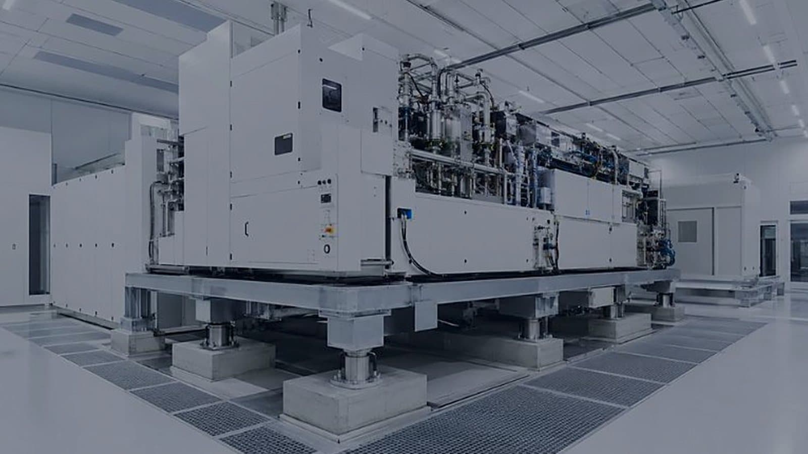
Clean-energy manufacturing has cleanroom problems. Lithium-ion cell production cannot tolerate moisture, so we design and build ultra-low-dew-point dry rooms to −60 °C dew point or lower; PV module and electrolyzer manufacturing need similarly controlled, high-purity environments.

Industries

Introduction

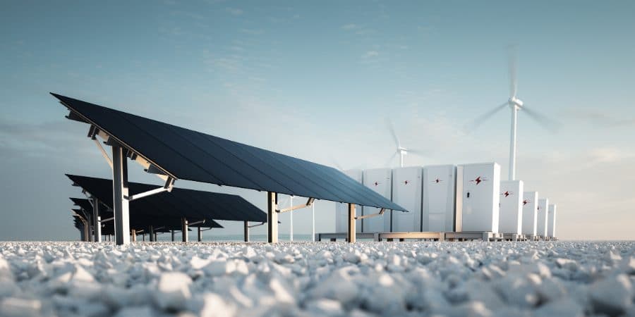
Around controlled manufacturing environments, we engineer the electrical backbone — LV to MV distribution, energy management, and integrated Solar–Wind–BESS installations delivered as one coordinated system rather than three procurements. Battery storage carries its own risk, so thermal management holds cells inside their safe operating window and the protection and detection strategy is designed with it, not after it.

Overview

Clean-energy manufacturing has cleanroom problems

Battery cells, electrolyzers and PV modules are made in environments as demanding as any pharmaceutical suite — and the failure mode is measured in yield, fire risk and warranty claims.

Lithium-ion cell manufacturing is, in engineering terms, a dry-room problem before it is anything else. Electrode and electrolyte handling cannot tolerate moisture: water reacts with the electrolyte and lithium salts, degrading capacity and cycle life and creating hazardous by-products. Holding a large production hall at a dew point of −40 °C or below, and −60 °C and below in the most sensitive areas, is a very different design problem from holding a comfort condition, and it dominates the energy consumption of the plant.

The same discipline applies further along the energy transition. Electrolyzer and fuel-cell production needs particulate control and high-purity utilities to protect membrane and catalyst layers. PV module assembly needs controlled, low-particulate conditions with ESD provision and stable lamination environments. Each of these is a controlled-environment problem with a manufacturing quality consequence.

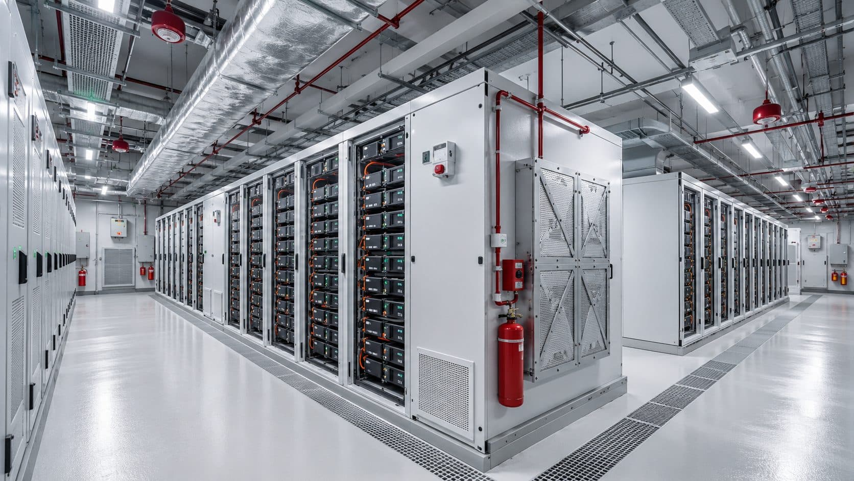
Battery energy storage brings a different set of risks. Cells have a narrow temperature window in which they deliver rated life; outside it, capacity fades quickly and the risk profile changes. Thermal management has to hold that window across an installation while remaining safe under fault, which means designing detection, off-gas and hydrogen monitoring, ventilation, explosion relief and suppression as one system rather than as separate packages.

Behind all of it sits the electrical infrastructure. Distribution up to 22 kV, power conversion, protection coordination, standby provision and SCADA-based energy management determine whether a hybrid generation and storage installation actually delivers stable, dispatchable power — and whether its performance can be measured and reported.

Capabilities

Scope of work

Controlled environments and robust power infrastructure for the energy transition — from battery gigafactory dry rooms to hybrid Solar–Wind–BESS systems engineered for efficiency, safety, and long-term performance.

Battery Gigafactory Dry Rooms

Lithium-ion cell production cannot tolerate moisture. We design and build ultra-low-dew-point dry rooms — to −60 °C dew point or lower — integrating high-capacity desiccant dehumidification with precise temperature and particulate control to protect electrode and electrolyte processes at gigafactory scale.

Hybrid Solar–Wind–BESS Integration

We engineer integrated Solar–Wind–Battery Energy Storage System (BESS) installations as complete, coordinated solutions. Our designs unify power conversion, thermal management, and safety systems — balancing intermittent generation with reliable storage to deliver stable, dispatchable clean power.

Power Distribution & Energy Management

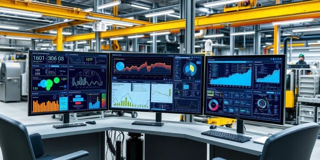
Reliable renewable infrastructure depends on a robust electrical backbone. We deliver LV-to-MV power distribution up to 22 kV, UPS and emergency power, and SCADA / IIoT-enabled energy management that monitors, optimizes, and reports performance in real time — targeting measurable reductions in energy consumption across the facility.

BESS Thermal Management & Safety Systems

Energy storage demands rigorous protection. We engineer precise thermal management to hold cells within their optimal window, integrated with fire detection and suppression, off-gas and hydrogen monitoring, and explosion-relief strategies — maximizing battery life while safeguarding people and assets.

Solar PV & Green Hydrogen Production Facilities

The next generation of clean-energy manufacturing needs controlled, high-purity environments. We engineer facilities for solar PV module assembly and green-hydrogen electrolyzer production — delivering the cleanrooms, clean utilities, and process infrastructure that protect product quality and process safety.

Sustainable & Energy-Efficient Design

Engineering responsibly is core to our practice. We apply energy modeling, airflow simulation, and IIoT-enabled monitoring to cut consumption without compromising performance — targeting a 30% reduction in HVAC energy use and supporting our clients' sustainability and ESG goals across the facility lifecycle.

Our approach

How an energy facility is engineered

The sequence applies whether the scope is a gigafactory dry room, an electrolyzer plant or a hybrid generation and storage installation.

  1. Process and duty definition

    For manufacturing, the moisture, particulate and thermal tolerance of each process step is established along with throughput and layout. For generation and storage, the load profile, generation mix, dispatch requirement, grid connection terms and site constraints are defined. This is what sets the duty everything else is sized against.

    Output

    • Process environmental requirement matrix
    • Load, generation and dispatch profile
    • Site and grid connection constraints
  2. Zoning, envelope and load reduction

    Dry-room air is the most expensive air in any factory, so the first design decision is how little of it is needed. Zoning separates ultra-low dew point areas from merely dry ones, and the envelope is designed for vapor tightness — airlocks, entry protocol, penetration sealing and construction detailing — because infiltration, not process load, is what usually drives desiccant plant size.

    Output

    • Environmental zoning plan
    • Vapor-tight envelope specification
    • Infiltration and moisture load calculation
  3. Dehumidification, thermal and safety design

    Desiccant dehumidification is designed with its pre-treatment, reactivation and heat recovery as one system, since reactivation energy dominates running cost. For storage installations, thermal management is designed to hold cells in their optimal window and is integrated from the outset with detection, off-gas and hydrogen monitoring, ventilation, explosion relief and suppression.

    Output

    • Dehumidification scheme and psychrometric analysis
    • Thermal management design
    • Fire protection, gas detection and explosion relief strategy
  4. Electrical, power conversion and controls

    Distribution up to 22 kV, power conversion, protection coordination, earthing, standby and UPS provision are designed together with the control and energy management architecture, so generation, storage and load are coordinated rather than merely connected.

    Output

    • Single-line diagrams and protection coordination
    • Power conversion and storage integration design
    • SCADA and energy management specification
  5. Construction, commissioning and performance verification

    Installation is inspected against hold points, and systems are commissioned and verified against the design duty — dew point stability under production conditions, thermal performance under load, safety system function, and generation and storage output against the modeled profile.

    Output

    • Commissioning records
    • Dew point and thermal performance verification
    • Safety system function test records
  6. Monitoring, optimization and lifecycle support

    Energy and performance monitoring is put to work: consumption is trended against output, plant is retuned against real operating data, and maintenance is planned around the assets that carry the process. Reporting supports sustainability and ESG obligations with measured data rather than estimates.

    Output

    • Energy monitoring and reporting framework
    • Optimization recommendations with expected savings
    • Maintenance and lifecycle support plan

Technical parameters

Design criteria

Typical requirements for clean-energy manufacturing and storage. Project values are fixed against the process and the dispatch requirement.

Battery dry rooms

Dew point, electrode and electrolyte areas−40 °C dew point and below; −60 °C and below for the most sensitive processes
Equivalent moisture contentApproximately 0.1 g/kg at −40 °C dew point, falling to roughly 0.01 g/kg at −60 °C
Dehumidification technologyDesiccant rotor with pre-cooling, staged reactivation and heat recovery
EnvelopeVapor-tight construction with sealed penetrations, airlocks and controlled entry protocol
Particulate controlCleanroom classification to ISO 14644-1 where the process requires it, typically ISO 7 to ISO 8
TemperatureStable production condition with tolerance set by the coating and calendering process

Battery energy storage — thermal and safety

Cell operating windowThermal management designed to hold cells within the manufacturer's optimal temperature band
Thermal uniformityCell-to-cell and rack-to-rack gradient limited to protect capacity and cycle life
Gas detectionOff-gas and hydrogen monitoring with staged alarm and ventilation response
Fire detection and suppressionEarly detection integrated with suppression and with the ventilation and isolation strategy
Explosion protectionDeflagration venting and relief strategy coordinated with enclosure design
VentilationNormal and emergency modes with defined changeover and fail-safe behavior

Electrical and power systems

DistributionLow voltage through medium voltage up to 22 kV
Power conversionInverter and converter integration for solar, wind and storage
Protection and groundingCoordinated protection study and grounding design to the connection requirement
ContinuityUPS and standby generation sized to the critical load schedule
Energy managementSCADA and IIoT-enabled monitoring, dispatch control and performance reporting

Energy efficiency and sustainability

HVAC energy targetDesign target of 30 % reduction in HVAC energy consumption against a conventional baseline
Heat recoveryApplied to desiccant reactivation and to process and exhaust streams where recoverable
Variable capacity plantVariable speed fans and pumps with demand-controlled ventilation in unoccupied periods
RefrigerantsLow-GWP selection consistent with local regulation and the client's ESG position
Measurement and reportingSub-metering and trending to support verified energy and sustainability reporting

Deliverables

What an energy project delivers

  • Process environmental requirement matrix and design basis
  • Environmental zoning plan and vapor-tight envelope specification
  • Infiltration and moisture load calculation with psychrometric analysis
  • Dehumidification scheme with reactivation and heat recovery design
  • Thermal management design for storage and process cooling
  • Fire and gas detection, ventilation and explosion relief strategy
  • Electrical single-line diagrams, protection coordination and earthing design
  • Power conversion and storage integration design
  • SCADA, energy management and reporting specification
  • Federated BIM model and issued-for-construction drawings
  • Commissioning records and verification of dew point and thermal performance
  • Safety system function test records
  • Energy monitoring framework and optimization recommendations
  • Maintenance strategy and lifecycle support plan

Compliance

Standards and reference practice

ISO 14644Cleanrooms and associated controlled environments
Classification and verification where the manufacturing process requires particulate control.
IEC 62933Electrical energy storage systems
Reference framework for storage system planning, safety and performance.
NFPA 855Installation of stationary energy storage systems
Separation, protection, detection, ventilation and explosion control practice for BESS.
IEC 62443Industrial automation and control system security
Applied to the control and energy management architecture.
IEC 60364 · IEC 61439Electrical installations and switchgear assemblies
Installation design basis and panel verification for LV distribution.
ISO 50001Energy management systems
Framework for measurement, target setting and continual improvement in energy performance.
ISO 45001 · ISO 14001Health, safety and environmental management
Site execution framework and environmental controls.
EN 1886 · EN 1822Air handling units and high efficiency filters
Casing classification and filter efficiency for the air systems serving controlled areas.

Talk to our engineers

Tell us about your facility and we will route your inquiry to the right engineering lead.

Insights

Technical notes from this practice

  • BESS thermal management, gas detection, explosion control and suppression often come from four suppliers, and each changes what the others must handle. Issuing the UL 9540A report with all four packages, naming one interface owner and choosing explosion control from the test data keeps them working as one system.

    InsightRead

  • In a Li-ion dry room at −60 °C dew point and below, extra air changes do not help: return air often passes back through the desiccant rotor, so more supply air means a bigger rotor and more regeneration heat. Size airflow from the moisture balance; pressure control, airlocks and envelope sealing carry over from pharma.

    InsightRead

  • At −60 °C dew point a coil would freeze, so a desiccant rotor does the drying and regeneration air, often heated to around 120–140 °C, is the running cost. Pre-cooling ahead of the rotor, heat recovery, staging with the real crew size and a tight envelope are all set at design stage.

    InsightRead

  • A failing lithium-ion cell vents hydrogen, CO, CO2 and solvent vapour before it burns. Hydrogen's LFL is 4% by volume, and exhaust is commonly sized to stay below 25% of the LFL. The first gas alarm should start the exhaust and isolate the rack; suppression release comes last.

    InsightRead

  • AMC limits: name the compound, then the unit

    HEPA and ULPA filters do not stop airborne molecular contamination, and an AMC limit written only as "1 ppb" is a different mass for every compound: about 0.70 µg/m³ for ammonia, 1.49 µg/m³ for hydrogen chloride. A fab URS should name the compound, the unit with its reference temperature, and the sampling method.

    InsightRead

  • Hybrid renewable sites often size battery cooling from the weather and lump the other auxiliaries into one allowance. Resistive heat in the cells rises with the square of the current, and a 3% loss on a 1 MW discharge is 30 kW of heat. Control rooms, fire and gas safety and site services need their own lines.

    InsightRead

  • At −60 °C dew point and 20 °C, a dry room sits near 0.05% RH. A drift to −40 °C dew point carries about twelve times the water yet reads only 0.55% RH, inside a general-purpose sensor's ±1 to ±2% error. That is why dry rooms are specified and alarmed in dew point.

    InsightRead

View all insights (40)

Technical resources

Free references for this work

The references we reach for ourselves. No sign-up, and where a figure comes from a standard, we name it.

Air change rate calculator

Room volume to required airflow, or the rate an existing supply delivers. In m³/h and CFM.

Open the tool

Questions

Renewable Energy — questions we are asked

Answered by the engineers who do the work.

Because water damages the product. Moisture reacts with the electrolyte and with lithium salts, reducing capacity and cycle life and generating hazardous by-products, and the required moisture level is far below what conventional cooling-based dehumidification can reach. Electrode and electrolyte areas typically need a dew point of −40 °C or below, and the most sensitive processes −60 °C or below. That requires desiccant dehumidification and a genuinely vapor-tight envelope.

Infiltration, more often than process load. Every leak, unsealed penetration and door opening admits ambient moisture that the desiccant plant then has to remove continuously, and in a humid climate that load is large. Zoning ultra-low dew point areas as tightly as possible, detailing the envelope for vapor tightness, and designing entry protocol and airlocks properly usually saves more capital and energy than any refinement of the plant itself.

By holding cells inside the manufacturer's optimal temperature window and keeping the gradient across the installation small, because uneven temperature ages cells unevenly and shortens the life of the whole system. The thermal design is developed together with the safety design — detection, off-gas and hydrogen monitoring, ventilation, explosion relief and suppression — since a thermal event and the response to it are the same engineering problem.

Yes. Hybrid installations are designed as a coordinated whole: generation, power conversion, storage, protection and control sized against the load profile and the dispatch requirement. The engineering that determines whether the installation is genuinely dispatchable is mostly in the control and energy management layer, not in the generating equipment.

It is a design target we work toward, measured against a conventional baseline for the same duty, and it is pursued on dry rooms through envelope tightness, zoning, staged dehumidification and heat recovery on reactivation air. The achievable figure depends on climate, process and how tightly the envelope can realistically be built, and we state the basis of the estimate rather than quoting the number without one.

Electrolyser and stack assembly needs particulate control to protect membrane and catalyst layers, high-purity utilities, and controlled handling environments — closer to a cleanroom than to a conventional factory. Alongside that sits the process safety engineering hydrogen demands: area classification, ventilation, gas detection and ignition source control designed together.

Through sub-metering and trending established during design, so consumption can be attributed to systems rather than read at the incomer. Performance is compared against the modeled baseline under real operating conditions, and the same data supports sustainability and ESG reporting with measured figures instead of estimates.