ISO 14644-3 allows installed filter leak scans by aerosol photometer or discrete particle counter. The photometer is quick but needs roughly 10 to 100 mg/m³ upstream; the counter works at far lower loads. For ULPA and filters you want kept free of oil, choose the counter method at design stage.
High-purity PVDF joined like ordinary plastic pipe leaves fusion beads that trap bacteria, so fab UPW loops use bead-and-crevice-free joints. UHP gas lines add electropolished 316L, orbital welds with coupons, helium leak tests and outlet particle, moisture and oxygen checks. Pharma WFI practice shares much of the discipline.
ISO Class 1 allows 10 particles of 0.1 µm and larger per cubic metre; ISO 5 allows 100,000 at that size. At that level the installed leak scan must prove frames and grid, not just the U15 filter, single-digit counts need large sample volumes, and airborne molecular contamination needs its own sampling plan.
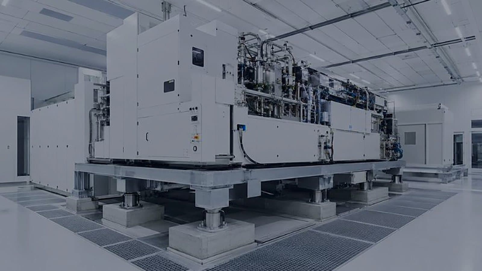
Lithography tools are often specified on the VC curves, where VC-D is 6.25 µm/s RMS. Fans, pumps and compressors reach the tool through the structure, so rotating plant location, tool floor type and flexible crossings belong in the layout, decided with the structural engineer before the slab is poured.
HEPA and ULPA filters do not stop airborne molecular contamination, and an AMC limit written only as "1 ppb" is a different mass for every compound: about 0.70 µg/m³ for ammonia, 1.49 µg/m³ for hydrogen chloride. A fab URS should name the compound, the unit with its reference temperature, and the sampling method.
EN 1822 ULPA classes add a nine each above H14: U15 99.9995%, U16 99.99995%, U17 99.999995% at MPPS. Semiconductor ISO Class 1 to 3 spaces need them. A pharma Grade A zone at ISO 5 rarely does, because people and seal leaks drive its counts; H14 with a sound seal usually carries it.
A 1,000 m² fab bay with FFUs over 90% of its ceiling holds about 1,250 units of 1,200 × 600 mm. After handover each is a motor on the BMS, and the design documents should group the units by tool and zone so the fault logic can tell a work order from an alarm.
At 21 °C and 50% RH, a sensor reading 0.5 K warm reports humidity about 1.5% RH low, most of a ±2% RH band. Wall sensors near doors read their corner, return-duct sensors lag, slow sensors make the loop hunt and drift takes the rest. Sensor position is a design decision.
SEMI F47 expects semiconductor tools to ride through sags to 50% for 200 ms, 70% for 0.5 s and 80% for 1 s. Fan drives, contactors and controls are often bought to no such curve, so the tool stays up while the cleanroom loses airflow. Specify the support systems to the same curve.
Micro-environments hold ±2% RH at the tool and let the room run a looser band. A 2 m³ enclosure at 0.4 m/s over 1 m² replaces its air every 5 seconds. Steady leakage is the harder case: with the room at 45% ± 5% RH, size the enclosure for 50% RH at the highest room temperature.
A filter that passed its factory scan can still fail the installed leak test at the frame. Gel-channel grids seal without clamp force and allow quick changes; gasket grids depend on even clamping and take a compression set. Gel usually suits Grade A and B; gaskets can suit Grade D.