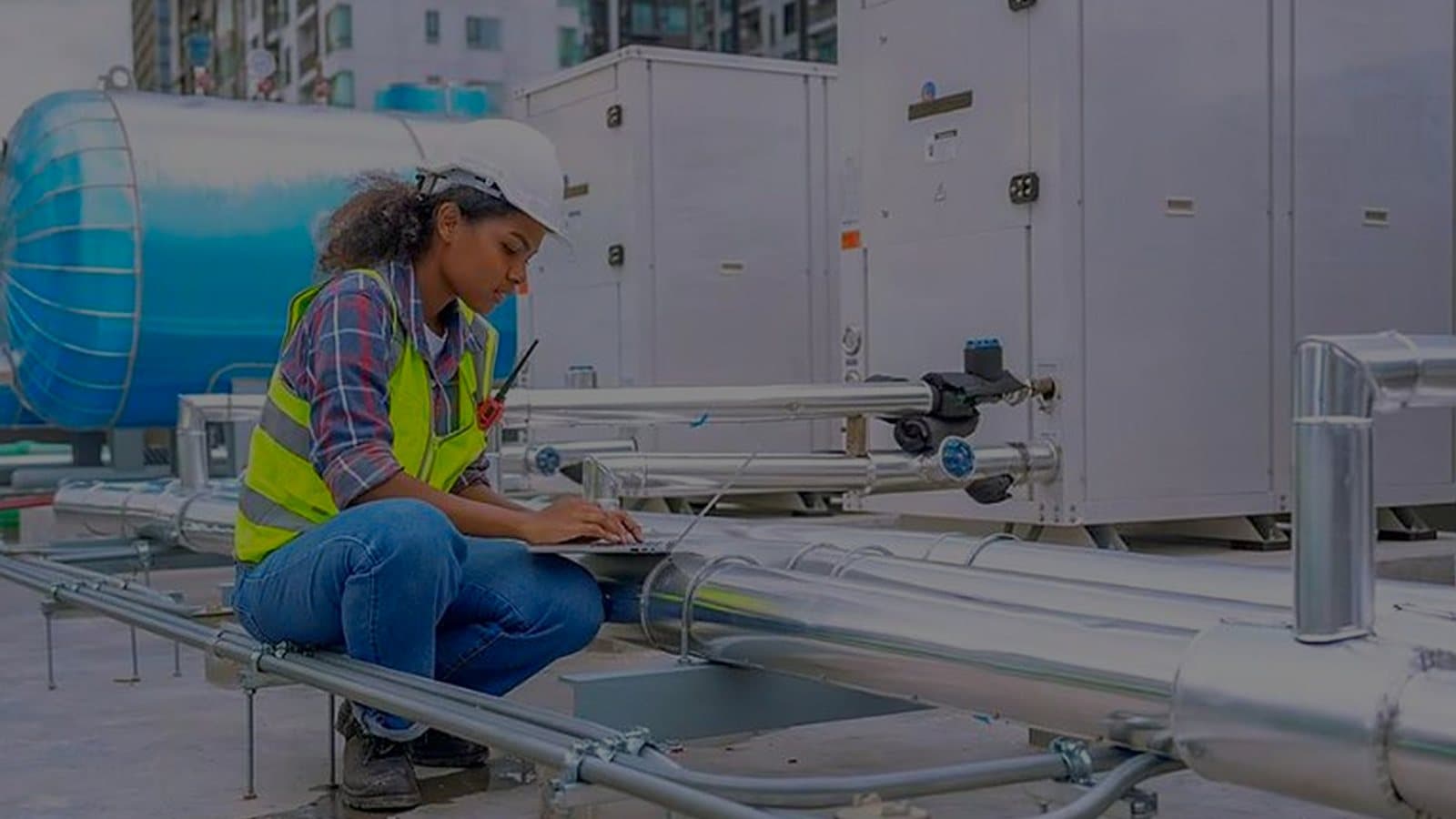
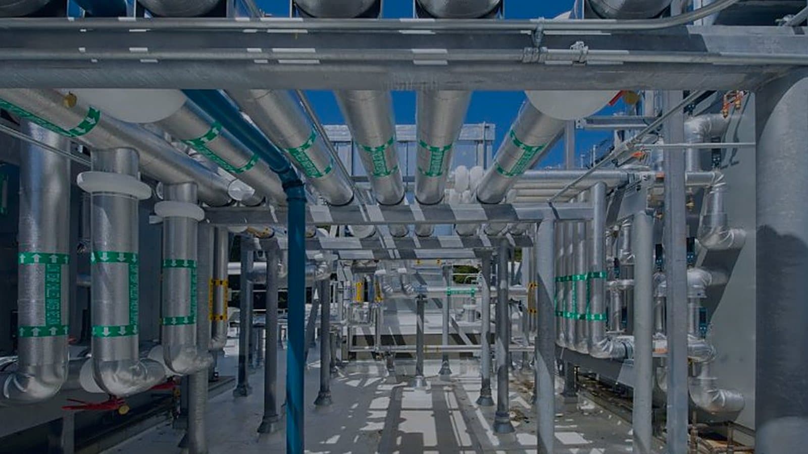
Filter withdrawal, coil pull space and fan replacement all need clearance that nobody draws by default. Dimensioning these zones on the AHU general arrangement drawing and carrying them into the BIM model keeps other trades out of them, and avoids a shutdown the first time a coil has to come out.
EN 1886 class L2 allows an AHU casing 0.44 l/s per m² of leakage at −400 Pa. On a witnessed FAT, casing leakage, fan airflow at design static pressure, filter bypass and the control panel are checked against the approved specification, and both engineers sign the sheet that goes into the equipment file.
Electric reheat is paid for twice, as heat and as the cooling that removed it. A wrap-around heat pipe reheats with no energy input but adds pressure drop: 100 Pa at 5 m³/s and 60% fan efficiency is about 833 W, every running hour. The comparison is a per-unit calculation.
Above about 2.5 m/s face velocity, a wet cooling coil carries water onto the next section, a microbial risk in a hygienic AHU. A smaller coil face saves casing size but adds an eliminator, higher pressure drop and fan energy. At 5 m³/s, 2.5 m/s needs a 2 m² face.
Recirculated cleanroom air returns near room condition and needs almost no dehumidification. In a worked wet-season example, 10,000 m³/h of fresh air costs about 186 kW of coil load. Remove avoidable fresh air from exhaust, leakage and over-pressurisation before investing in heat recovery devices.
Under EN 779, F9 was a filter class: 95% or more at 0.4 µm. Under EN 1886, F9 is a casing class: at most 0.5% of the airflow bypassing the filter frames. Specify filter stages to ISO 16890 or EN 1822 and the casing bypass class on its own line.
When the fresh-air unit does all the drying and room AHU coils stay dry, every room's humidity depends on that one unit. Size its coil on the wet-season coincident condition, control on off-coil dew point, and decide in the design basis what happens when it trips.
Filter loading can swing AHU resistance from 250 Pa clean to 450 Pa at change-out while airflow must stay constant. Selecting near 350 Pa and checking design airflow at 450 Pa with the drive at full speed avoids both a fan stuck right of peak and an airflow shortfall. The energy difference is modest.
A 10 m stairwell at a 10 K temperature difference produces about 4 Pa of stack effect, and a door near the top or bottom can see up to half of it, a noticeable part of a 10–15 Pa cascade step. Shafts that open onto clean corridors make the cascade drift with floor, weather and door position.
A 20 °C / 45% RH room has a dew point near 7.7 °C. A recirculation coil on 12 °C water stays dry; on 6 °C water it condenses, dehumidifies against the fresh-air unit and needs a wet drain pan. The dry coil is larger and needs a second water temperature.
A chilled-water valve with 10 kPa across it on a 40 kPa coil branch has an authority of 0.2. At part load it sits near its seat, hunts, and the cleanroom dew point swings. Size the valve drop close to the branch drop, aim near 0.5, and check the opening at minimum load.