A fan wall keeps a GMP supply unit running when one fan fails, provided each fan has a backdraft damper so air cannot flow back through the stopped one. Each EC fan's rectifier adds harmonics, THDi around 35–42% with a DC choke. A single plug fan is simpler but needs a standby.
Either way an FFU filter is changed, the room stops for the room-side leak scan, cleaning and recovery. Top-side replacement needs a walkable ceiling and disturbs the plenum; room-side replacement brings the loaded filter out through the classified space. Both need upstream injection and sampling ports that can be reached.
Clean AHU cooling coils from the leaving face with low-pressure water or steam and an approved, fully rinsed detergent, after checking the drain. Take the frequency from the coil's pressure drop trend against a commissioning baseline, and record the method, detergent batch, before and after readings and photos of both faces.
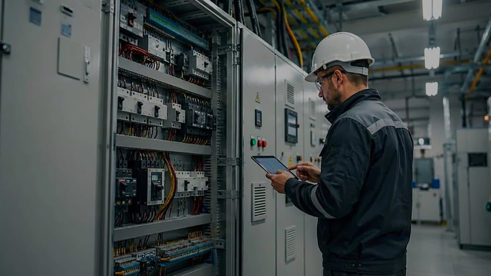
A control panel FAT is the last time every wire is reachable and the drawings are on the table. Use it for IEC 61439-1 routine verification, point-to-point I/O, interlocks, alarm texts and approved software versions. The same fault found during site loop checks costs a day instead of minutes.
Drums routed through a personnel airlock months after start-up are a layout-stage mistake. Small items go through a pass box; carts and drums need a material airlock, a room with its own air, cleaning step and place in the 10 to 15 Pa cascade. Check size, then frequency, then pressure.
On an equipment-only AHU purchase, write the EN 1886 casing leakage class and F9 filter bypass into the order, witness the leakage test on the built unit at FAT, check the selection against the project airflow schedule, and require the equipment file compiled during production so IQ starts complete.
Standing water under a cooling coil is the classic growth source in an AHU. A hygienic unit adds a drain pan that empties completely, smooth closed inner surfaces, full-size access doors, filter bypass class F9 to EN 1886, removable parts and a complete equipment file. Write each into the specification as a FAT check.
IEC 61439 temperature-rise verification assumes an ambient up to 40 °C with a 24-hour average of 35 °C. A hotter plant room is a special service condition the user should declare, so the builder verifies or derates for it. The specification should also size ventilation for the real losses and add drive heat.
A new coil and fan inside an old AHU casing keep every gap and hygiene defect of that casing. Pressure-test it against the EN 1886 class a new unit would meet and read the result by section: below plant-room pressure, gaps pull unfiltered air in, and worn filter frames let air bypass the filters.
"Type-tested" is IEC 60439 wording. IEC 61439-1 separates design verification (Clause 10), which proves the assembly system once, from routine verification (Clause 11), which checks every panel built. At FAT a buyer should receive the design verification report and a routine record tied to the panel serial number.
Steam that has not absorbed before it meets a filter, fan or sensor leaves them wet. Take the absorption distance from the maker at the unit's real air speed and load, keep wet-sensitive parts beyond it, fit a trapped stainless drain pan and access, and add a downstream high-limit sensor.
Warranty terms usually decide which chiller and AHU work goes to the OEM, and the split is rarely revisited. Keep compressor, refrigerant and firmware work with the OEM, bring filters, cleaning, trending and first response in-house, and file every service report in the site CMMS under change control.