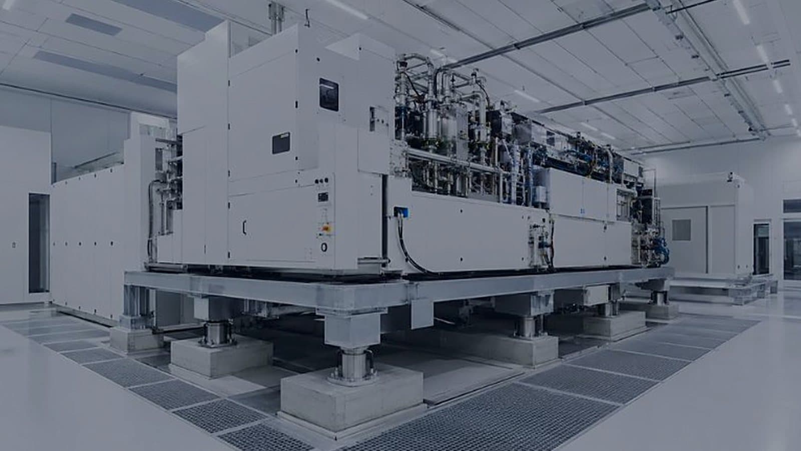
An FFU array can average 0.45 m/s and still have a corner at 0.30 m/s. Measure each unit on a grid at FAT with fan speed settings recorded, then repeat the grid across the installed array at OQ. A flat map is healthy; a low edge points at speed, plenum, blanking or lights.
EN 1886 classes AHU casing strength by deflection at test pressure: D1 up to 4 mm/m, D2 up to 10 mm/m. On a high-static GMP supply unit, a flexing panel works its gaskets loose and leakage rises. Ask which class was tested, on what model box, and whether your design pressure fits.
Air through a 25% open floor panel moves 4 times faster than the downflow above it, and that pressure drop keeps a fab bay's airflow vertical. Use less open area near return chases, solid panels under tools with rebalancing around them, sealed cut-outs, and check with a smoke study after tool install.
A spring isolator with its transport bolt still fitted transmits everything. Remove transport locks, select isolators for the lowest drive speed, keep flexible connections slack, remove rigid bridges such as conduit or drain lines, use inertia bases where needed, and file the balance report and a vibration baseline.
An AHU's section split and weight are set by the tightest point on its delivery route: door clear openings, lift car and rated load, corridor corners, crane reach and floor loading. Survey the route before the general arrangement is frozen, and plan a casing leakage check after site reassembly.
Put containment exhaust fans at the end of the run so ducts inside the building stay negative. Run duty and standby with isolation dampers and alarmed changeover, discharge vertically with height and velocity from a standard or a dispersion study, and keep the plume away from fresh-air intakes.
A pre-filter changed at 150 Pa on a 0–1,000 Pa gauge sits in the bottom 15% of the dial with about 20 Pa of uncertainty. A 0–250 Pa gauge puts it at 60% with 5 Pa. Range each stage's gauge and transmitter to its own change point.
An AHU casing is described by five EN 1886 classes: strength D1–D3, leakage L1–L3, filter bypass up to F9, thermal transmittance T1–T5 and thermal bridging TB1–TB5. A witnessed FAT can test leakage on the real unit; transmittance and bridging come from a laboratory model box, so the model box report belongs with the offer.
A V-belt sheds rubber dust into the airstream for its whole life, and in a GMP supply AHU that dust loads the final filters. Belt drives also lose a few per cent of shaft power and need regular tensioning. Direct-drive plug fans avoid all three, though a large belt-driven housed fan can still win at high pressure.
When a supply AHU trips with extract fans running and dampers open, a Grade B room loses its 10–15 Pa margin and pulls air from the lower grade. Tight-shutoff dampers with a tested leakage class, defined fail positions, interlocks, proven position and a supply-first restart keep the cascade, and a deliberate fan trip at FAT proves it.
An air shower blows loose fibres off the outside of a coverall and interlocks two doors. It does nothing about what operators shed from underneath. It earns its place at powder-area entries and interlocked routes, and it should never be the reason a gowning step disappears from the procedure.
A fixed-speed fan filter unit loses airflow as its HEPA filter loads. Set at 0.45 m/s, it has 20% to lose before the 0.36 m/s bottom of the Annex 1 guidance range. Constant-airflow EC units hold velocity if they are selected at the final pressure drop, and their speed trend doubles as a filter-loading record.